DMA
Introduction
The Direct Memory Access (DMA) peripheral allows data transfers with reduced CPU interaction.
It can perform transactions of data between peripherals and memory, or memory-to-memory (as a memcpy would).
The CPU is required to configure the transaction, but once launched it is free to go to sleep, process the incoming data or do anything else.
This unit is capable of performing complex tasks that can significantly impact on the performance and power consumption of memory-intense applications. It can be configured to perform 1D or 2D transactions and it can apply zero padding and perform transpositions on-the-fly, reducing the overhead of matrix operations. Furthermore, it supports tightly-coupled stream accelerators which can process data as it flows through the DMA, thus improving both latency and memory consumption.
The DMA Hardware Abstraction Layer (HAL) facilitates the configuration of transactions from the users application. Furthermore, it adds an additional layer of safety checks to reduce the risk of faulty memory accesses, data override or infinite loops.
The DMA SDK, on the other hand, offers user-friendly functions for essential memcpy and fill operations. It does not include the validation capabilities of the HAL nor the 2D and padding features, prioritizing performance at the cost of an increased risk of inconsistencies.
Structural description
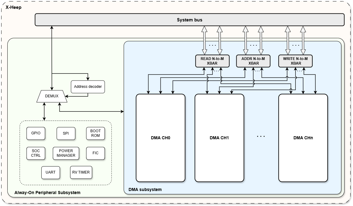
Figure 1: General structure of the DMA subsystem in X-Heep
Getting started with the DMA
This peripheral has been designed to suit the need of a wide spectrum of applications, following the main design principles of X-HEEP: configurability and extendibility.
For this reason, each DMA feature is fully configurable, enabling the user to explore the area-performance design space with more precision.
Furthermore, the DMA can communicate and interface with peripherals and accelerators in a variety of eays, providing all the flexibility that designers need.
The following paragraphs will describe and explore in detail each aspect of this system, providing examples and thorough explanations.
To get started, this is a general overview of various aspects that defines the DMA.
P are high-level parameter-defined features; P! are SystemVerilog-level parameter-defined features; X provides extendability; B base features, always accessible.
Custom interface with peripherals & accelerators
X
From a purely structural point of view, the DMA has been designed by self-sufficient units, i.e. units that perform one particular set of functions and are as independent from one another as possible. An example of this design principle is the redundancy in the counters that keeps track of the progression of the transaction: each unit has its own, which means that each unit works on its own account. This increases the robustness of the design, at the cost of some area for additional counters. These are the four units that constitutes the DMA system:
Read Unit: Reads data from the system bus using the OBI protocol, performs sign-extension and pushes data into the read FIFO.
Processing Unit: Pops data from the read FIFO, processes it (i.e. performs zero-padding) and pushes it into the write FIFO. If a tightly-coupled accelerator is present, data can be instead pushed into the accelerator using the HW FIFO interface.
Write Unit: Pops data from either the write FIFO or the tightly-coupled accelerator output FIFO, casts it to the output datatype and puts it on the system bus using the OBI protocol. Additionally, it can use as destination address the data coming from the address FIFO.
Read Address Unit: Reads data from the system bus using the OBI protocol and pushes data into the read FIFO. This data can be used with the Address Mode as destination addresses for the transaction.
Buffer Unit: Includes all the FIFOs of the DMA System and the related logic.
Depending on the configuration, some of these units can be modified or even removed completely, along with linked configuration registers.
DMA channels layout
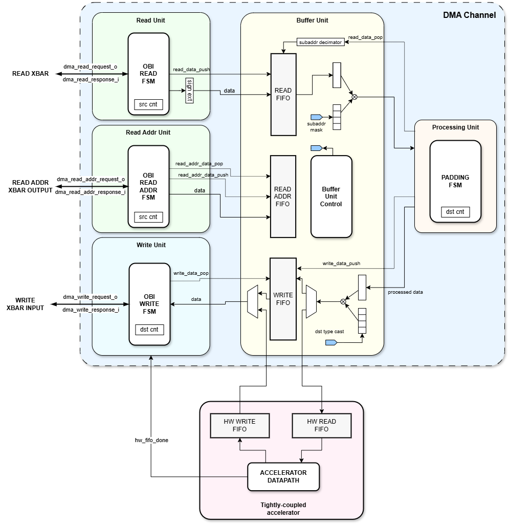
Figure 2: Structure of a DMA channel, including a tightly-coupled accelerator
The DMA subsystem is composed of a parametrized number of control units called channels, configurable in mcu_cfg.hjson.
Each channel can be configured, by the CPU or by an external controller, to perform a transaction, independently of the state of other channels.
N-channels are connected to a N-to-M bus that exposes M-master ports on the system bus. Multiple channels can thus perform multiple transactions in parallel, a feature that enables memory-intense applications to increase their throughput.
There are several ways to connect N-channels to the system bus through M-master ports.
e.g. Let’s consider a DMA subsystem with N = 4 channels and M = 2 master ports.
There are two possible solutions:
CH0, CH1 connected to port 0 & CH2, CH3 connected to port 1
CH0, CH1, CH2 connected to port 0 & CH3 connected to port 1
In order to specify one among these configurations, the user has to set the num_channels_per_master_port parameter in mcu_cfg.hjson, which defines the maximum channels per master port ratio.
The first configuration of the previous example has 2 channels per master port, so a channels per master port ratio of 2. On the other hand, the second solution has a ratio of 3: the first 3 channels are connected to port 0, while the remaining channel is connected to the remaining port 1.
While the 1st solution is a general purpose, balanced configuration, the 2nd solution might be better suited for applications that need a low latency channel for high priority tasks.
This mechanism guarantees maximum flexibility, enabling the user to adapt the DMA subsystem to its requirements, both in terms of area and performance.
Interrupts
If enabled, a transaction interrupt is raised every time a DMA transaction is completed. However, due to architectural limitations, there is only a single transaction done signal for the entire DMA subsystem.
To allow users to identify which channel raised the transaction interrupt, an interrupt flag register system has been developed. Here’s how it works: when a DMA channel completes its transaction and the interrupt enable register is correctly set, the transaction IFR (Interrupt Flag Register) is set. This register is designed to be cleared automatically once read, which is convenient as it eliminates the need for an additional register write.
The transaction interrupt handler leverages this mechanism to identify the channel that raised the interrupt. As soon as an IFR is read as high, it triggers the actual handler, which can be redefined by the user. An example of this mechanism at work is explained in Example 7.
It is possible that a channel could raise an interrupt while the CPU is processing a previous interrupt from another channel. This is not an issue because the IFR will remain set until the CPU reads its content. However, this situation could introduce additional delay to the execution of the application.
For this reason, the handler implemented by the user should be as brief as possible.
Data FIFOs configuration
Each DMA channel uses FIFOs to buffer the data to be read and written, which is crucial for mitigating the combined delays from the system bus and the Always On Peripheral Bus (AOPB).
The size of the FIFOs is parametric and is the same across all channels.
Some applications can benefit from larger FIFOs because it allows for more values to be buffered in situations where the bus is heavily utilized or the target peripheral, such as the SPI, is too slow. On the other hand, other applications might not require such large FIFOs, so area can be saved by reducing its size.
It is possible to specify the size of the DMA FIFOs in mcu_cfg.hjson, by modifying the fifo_depth parameter.
Advanced Data Processing
The DMA can perform complex tasks such as 2D transactions and it can apply zero padding and perform transpositions on-the-fly, reducing the overhead of matrix operations. However, as always, performance costs area occupation. If needed, the zero padding feature can be disabled by modifying the mcu_cfg.hjson parameter zero_padding_en: "yes" to zero_padding_en: "no". This will eliminate entirely the processing unit, which takes care of the zero padding feature. However, the 2D transactions feature will still be present, as it is managed by the read unit and write unit.
Triggers
In the case of memory-peripheral operations, it is common for the peripheral to have a reaction time that cannot match the system clock. For example, the SPI transmits data with a period of circa 30 clock cycles.
This difference in response times creates the need for a communication channel between DMA subsystem and peripheral allowing the DMA operations to be suspended according to the peripheral state. These signals are called triggers.
They can be used both when the peripheral writes data using the DMA and when the DMA reads data from the peripheral. The DMA can be configured to respond to triggers by enabling the appropriate slot via software, using the DMA HAL.
Always-On Peripheral Bus
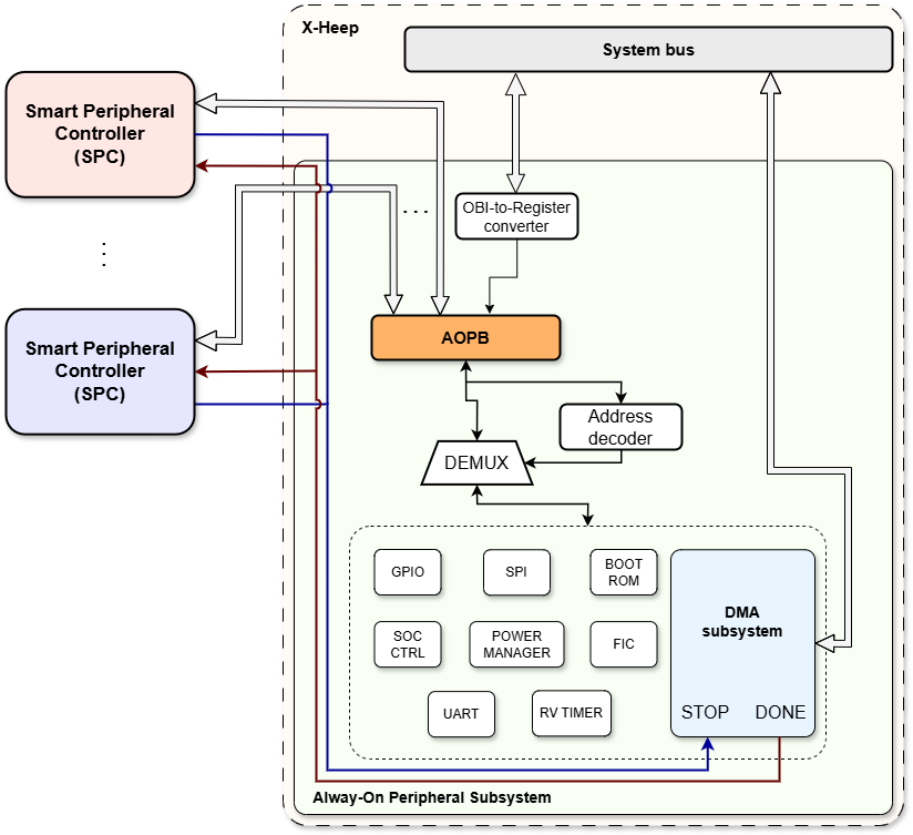
Figure 3: Structure of the DMA system with AOPB and SPCs
This is a low-complexity bus that exposes the register interface of the units in the Always-On subsystem to any Smart Peripheral Controller (SPC), i.e. external accelerators. In this way, accelerators can bypass entirely the system bus.
In the case of the DMA subsystem, this feature allows designers to configure the DMA subsystem without any CPU action, reducing power consumption while at the same time increasing the performance and effectiveness of the accelerator.
Check out the im2col SPC in the hw\ip_examples folder for a detailed example, along with Tommaso Terzano’s Master Thesis, which developed this unit (https://webthesis.biblio.polito.it/33222/).
Tightly-coupled Accelerator Interface (HW FIFO)
The DMA can support tightly-coupled accelerators via a simple push&pop interface, defined in fifo_pkg.sv in ``hw/core-v-mini-mcu/include`.
Functionally, the accelerator is completely transparent to the DMA system, as the accelerator is required to have both an input and an output FIFO: the DMA Processing Unit will push data into the accelerator’s input FIFO and the Write Unit will pop data from the accelerator’s output FIFO.
The other crucial requirements for tightly-coupled accelerators is to provide a done signal. This is particularly necessary (and useful) for accelerators that read N words and outputs M words, such as down-samplers used in Edge AI.
A part from this interface, there are no limits on the accelerator structure itself.
Check out the digital Level Crossing example in the hw\ip_examples folder for a detailed example.
A block diagram showing this DMA interface along with an external accelerator is shown in figure 1.
Registers description
This section will describe every register of a DMA channel and their function. The complete address of a DMA channel register is the following:
DMA_START_ADDRESS + DMA_CH_SIZE * channel + REGISTER_OFFSET
The previous parameters, including the register offsets, can be found at sw/device/lib/runtime/core_v_mini_mcu.h and sw/device/lib/drivers/dma/dma_regs.h
|-------------- 31 : 0 -------------|
|-------------- PTR_IN -------------|
SRC_PTR_REG
SW access: rw
Description: contains the pointer to the source, which could either be data stored in memory or a peripheral.
|-------------- 31 : 0 -------------|
|------------- PTR_OUT -------------|
DST_PTR_REG
SW access: rw
Description: contains the pointer to the destination, which could either be data stored in memory or a peripheral.
|-------------- 31 : 0 -------------|
|------------- PTR_ADDR ------------|
ADDR_PTR_REG
SW access: rw
Description: Used only with the address mode . It contains the pointer to the source, which in this case must data stored in memory. It will be removed if the address mode is disabled.
|---- 31 : 14 ----|---- 15 : 0 ----|
|--- Reserved ----|----- SIZE -----|
SIZE_D1
SW access: rw
Description: number of elements (not bytes) to be copied by the DMA channel along the first dimension, i.e. using the first counter. As soon as this register is written, the transaction starts.
|---- 31 : 14 ----|---- 15 : 0 ----|
|--- Reserved ----|----- SIZE -----|
SIZE_D2
SW access: rw
Description: number of elements (not bytes) to be copied by the DMA channel along the second dimension, i.e. using the second counter.
|---- 31 : 2 ----|--- 1 ---|--- 0 ---|
|--- Reserved ---|- WIN_DN |-- RDY --|
STATUS
SW access: ro
Description: this register is used by the DMA to communicate the status of the transaction. READY is 0 when the DMA is busy performing the transaction, 1 otherwise.
|---- 31 : 6 ----|---- 5 : 0 ----|
|--- Reserved ---|----- INC -----|
SRC_PTR_INC_D1
SW access: rw
Description: increment in bytes to apply to the source pointer for every copied element.
|--- 31 : 23 --|---- 22 : 0 ----|
|-- Reserved --|------ INC -----|
SRC_PTR_INC_D2
SW access: rw
Description: increment in bytes to apply to the source pointer every time a “row” is copied, in order to go to the new line. It’s necessary only for 2D transactions. From an application perspective, this value has to be computed depending on the size of the input matrix and the 2D stride. Check the functional description paragraph for more information or Example 4.
|---- 31 : 6 ----|---- 5 : 0 ----|
|--- Reserved ---|----- INC -----|
DST_PTR_INC_D1
SW access: rw
Description: increment in bytes to apply to the destination pointer for every copied element.
|--- 31 : 23 --|---- 22 : 0 ----|
|-- Reserved --|------ INC -----|
DST_PTR_INC_D2
SW access: rw
Description: increment in bytes to apply to the destination pointer every time a “row” is copied in order to go to the new line. It’s necessary only for 2D transactions. From an application perspective, this value has to be computed depending on the size of the output matrix and the 2D stride. Check the functional description paragraph for more information.
|---- 31 : 16 ----|---- 15 : 0 ----|
|----- TX_TRG ----|---- RX_TRG ----|
SLOT
SW access: rw
Description: identifies the triggers for which the DMA channel will stall in writing and/or reading operations.
|---- 31 : 2 ----|---- 1 : 0 ----|
|--- Reserved ---|---- DATA_T ---|
SRC_DATA_TYPE
SW access: rw
Description: defines the source data type using this scheme:
0: word, i.e. 4 bytes
1: half word, i.e. 2 bytes
2 or 3: byte
|---- 31 : 2 ----|---- 1 : 0 ----|
|--- Reserved ---|---- DATA_T ---|
DST_DATA_TYPE
SW access: rw
Description: defines the destination data type using this scheme:
0: word, i.e. 4 bytes
1: half word, i.e. 2 bytes
2 or 3: byte If wider than the source datatype and sign extension is enabled, the output data will be sign extended
|---- 31 : 1 ----|---- 0 : 0 ---|
|--- Reserved ---|---- SGND ----|
SIGN_EXT
SW access: rw
Description: enables the sign extension, which can be performed only if the output datatype is wider than the source datatype
|---- 31 : 2 ----|--- 1 : 0 ---|
|--- Reserved ---|---- MODE ---|
MODE
SW access: rw
Description: defines the operation mode of the DMA channel, following this scheme:
0: linear mode
1: circular mode
2: address mode
3: subaddress mode
|---- 31 : 1 ----|---- 0 : 0 ----|
|--- Reserved ---|---- HW_FIFO_MODE ---|
HW_FIFO_MODE
SW access: rw
Description: enables the HW FIFO mode, i.e. tightly-coupled accelerators
|---- 31 : 1 ----|---- 0 : 0 ----|
|--- Reserved ---|--- DIM_CFG ---|
DIM_CONFIG
SW access: rw
Description: defines the dimensionality of the transaction, i.e. if the transaction is 1D (DMA_DIM = 0) or if it is 2D (DMA_DIM = 1).
|---- 31 : 1 ----|--- 0 : 0 ---|
|--- Reserved ---|---- INV ----|
DIM_INV
SW access: rw
Description: enables the transposition of the input source, only with 2D transactions.
|---- 31 : 6 ----|--- 5 : 0 ---|
|--- Reserved ---|---- PAD ----|
PAD_TOP/BOTTOM/RIGHT/LEFT
SW access: rw
Description: defines the size of the padding to be applied to the source, in data units. They will be removed if the zero-padding feature is disabled.
|---- 31 : 13 ---|--- 12 : 0 ---|
|--- Reserved ---|---- W_SZ ----|
WINDOW_SIZE
SW access: rw
Description: defines the size of the window to be copied.
|---- 31 : 8 ----|---- 7 : 0 ---|
|--- Reserved ---|---- W_CNT ---|
WINDOW_COUNT
SW access: ro
Description: indicates the number of times the end of the window was reached since the beginning of the transaction.
|---- 31 : 2 ----|-- 1 ---|-- 0 ---|
|--- Reserved ---|- W_DN -|- T_DN -|
INTERRUPT_EN
SW access: rw
Description: enables the interrupt for window and/or transaction done.
|---- 31 : 1 ----|--- 0 : 0 ---|
|--- Reserved ---|--- FLAG ----|
TRANSACTION_IFR
SW access: r0
Description: interrupt flag register for transaction interrupts. It is set to ‘1’ when the transaction interrupts are enabled and the transaction is completed. It is cleared when it’s read by the CPU in the IRQ handler. This feature enables the handler to identify which channel raised the interrupt, as explained here.
|---- 31 : 1 ----|--- 0 : 0 ---|
|--- Reserved ---|--- FLAG ----|
WINDOW_IFR
SW access: r0
Description: interrupt flag register for window interrupts. It is set to ‘1’ when the window interrupts are enabled and the window is done. It is cleared when it’s read by the CPU in the IRQ handler.
Functional description
Dictionary
The implementation of the software layer introduced some concepts that need to be understood in order to make proper use of the DMA’s functionalities.
Transaction
A transaction is an operation to be performed by the DMA. It implies copying bytes from a source pointer into a destination pointer. The transaction configuration can be cross-checked before loading it into the DMA registers to avoid potential issues. The transaction starts only when the size of the first dimension, i.e. 1D, of the transaction is written in its corresponding register. The transaction is finished once the DMA has sent all its bytes (which not necessarily means they have been received by the final destination) or when the external stop signal is asserted.
While a transaction is running, new transactions can be validated, loaded and launched, provided they are not targeting the same DMA channel.
Transactions can be re-launched automatically in circular mode.
Once the transaction has finished, a status bit is changed (that can be monitored through polling) and a fast interrupt is triggered. The channel that raised the interrupt is identified and it’s passed to the the handler itself, which can be redefined by the user, as shown in Example 7 or in example_dma_multichannel in the application folder.
Source and destination
Sources and destinations are the two pointers that will exchange data. Bytes will be copied from the source and into the destination address.
Data type
The DMA allows transactions in chunks of 1, 2 or 4 Bytes (Byte, Half-Word and Word respectively). The size in bytes of the chosen data type is called data unit (usually abbreviated as du).
For example, 16 bytes can be 16 data units if the data type is Byte, but 8 data units if the data type is Half Word.
Source and destination can have different data types and if the destination type is larger than the source type, data can be sign extended.
Sign extension
It can be enabled by setting the bit in the corresponding register. If the destination data type is larger than the source type, the source data is sign extended to fill up the size of the destination data type.
Dimensionality
The DMA can perform both 1D transactions and 2D transactions. In a 1D transaction, the DMA copies a certain number of elements from the source pointer to the destination pointer using a single increment. On the other hand, in a 2D transaction the DMA copies data from the source pointer to the destination pointer using two separate increments, which can be interpreted as a 1D and a 2D increment. In this way, two-dimensional data manipulations, i.e. matrix manipulations, can be performed in a single DMA transaction.
Increment
In a 1D transaction, setting the increment appropriately can be leveraged to achieve non-contiguous read and/or write operations.
For example, let’s consider an array of 4 word-type elements. To copy just the first 2 bytes of each word, follow these steps:
Set the datatype of the transaction to half word.
Set the source increment to 2 data units.
Set the destination increment to 1 data unit.
After each reading operation, the DMA will increment the read pointer by 4 bytes (2 data units) and the write pointer by 2 bytes.
In the case of 2D transactions, a second increment must be set to perform matrix manipulations. The 2D increment can be interpreted as the number of words that the DMA has to “skip” to move to the next row of the matrix.
For example, let’s examine the extraction of a contiguous 2x2 matrix from a 4x4 matrix.
	| 3 | 5 | 7 | 9 |
	| 2 | 4 | 6 | 8 |           ->           | 3 | 5 |
	| 1 | 3 | 5 | 7 |                        | 2 | 4 |
	| 0 | 2 | 4 | 6 |
The total number of elements copied from the source is 4. In order to achieve this result, these are the setup of the increments:
For the source:
1D increment set to 1 word
2D increment set to 3 words
For the destination:
1D increment set to 1 word
2D increment set to 1 word
Moreover, by exploiting the 2D increment, it is possible to implement a 2D non-continuous read and/or write.
Detailed formulas for the computation of 2D increments are reported in the example application in the \example_dma_2d folder.
Zero padding
The DMA is capable of performing zero padding on the extracted data, both in 1D and 2D transactions, within a single transaction. This is achieved by setting four padding parameters:
Top
Bottom
Left
Right
e.g. Let’s consider a 2x3 matrix:
	| T | T | T | T | T |
	| L | x | x | x | R |
	| L | x | x | x | R |
	| B | B | B | B | B |
It’s important to highlight that the padding is performed (conceptually) only after the matrix has been extracted. So the padding parameters refers only to the extracted matrix, not to the entire source matrix.
Let’s revisit the previous 2x2 extraction example, this time adding a left and top padding of 1 element:
| 3 | 5 | 7 | 9 |                        | 0 | 0 | 0 |
| 2 | 4 | 6 | 8 |           ->           | 0 | 3 | 5 |
| 1 | 3 | 5 | 7 |                        | 0 | 2 | 4 |
| 0 | 2 | 4 | 6 |
Alignment
When performing transactions with bytes, the DMA can read/write from any pointer. However, if the data type is larger, words should be aligned so the DMA can perform a read/write operation and affect only the chosen bytes. If a word or half-word’s pointer is not a multiple of 4 or 2 (respectively), the pointer is misaligned. In some cases the DMA HAL can overcome this problem by reducing the data type (which will reflect on an efficiency loss).
Environment
An environment is a user-defined region of memory that informs the HAL of permissible read/write areas. This ensures that the DMA does not interfere with reserved memory regions.
Read and write permissions are not supported by environments. If an environment is defined, the DMA will have both read and write access to it.
Target
A target is either a memory region or a peripheral that the DMA can read from or write to. When targets point to memory, they can be assigned an environment to ensure compliance with memory restrictions.
Targets include:
A pointer (either a memory location or the Rx/Tx buffer for peripherals)
A size to be copied (if used as a source)
A data type
An increment
Configuration flags
During the creation or configuration of environments, targets or transactions, there could be inconsistencies or threatening situations (like writing outside the boundaries of a defined region). To provide the user with information about this potentially harmful situations, configuration flags are set while creating each of these entities. They can be unmasked and checked.
In some cases, when the threat is too risky, a crucial error might be raised and the operation of the configuration is halted.
If senseless configurations are input to functions, assertions may halt the whole program. This is reserved for extreme situations that mean the program was not properly coded (e.g. a slot value is provided and is not among the available ones).
Transaction modes
There are four different transaction modes:
Single Mode: The default mode, where the DMA channel will perform the copy from the source target to the destination, and trigger an interrupt once done.
Circular mode: It takes full advantage of the speed and transparency of the DMA. When selected, the DMA will relaunch the exact same transaction upon finishing. This cycle only stops if by the end of a transaction the transaction mode was changed to single. The CPU receives a fast interrupt on every transaction finished.
Address Mode: Instead of using the destination pointer and increment to decide where to copy information, an address list must be provided, containing addresses for each data unit being copied. It is only carried out in single mode. In this mode it’s possible to perform only 1D transactions.
Subaddress Mode: In this mode, the DMA can be configured to transfer words, half words or bytes from Flash to the destination target via the SPI slot. This mode is particularly useful as it allows the DMA to sequentially read the half words or bytes composing the word retrieved from Flash, and forward them to the appropriate location in the destination target. The key difference between Subaddress Mode and Single Mode in terms of SPI-Flash interaction lies in how data is handled. In Single Mode, when the destination data type is set to Half-Word or Byte, the DMA writes only the least significant half-word or byte from the word fetched via SPI. In contrast, Subaddress Mode ensures that each half-word or byte within the fetched word is considered and transferred correctly to the destination.
Tightly-Coupled FIFO-Based Accelerator Interface
By setting the correct enable register, the DMA can fetch data from the source target and forwards it directly to an external accelerator tightly coupled with the DMA itself. Using this interface, the DMA can interact with an external streaming accelerator through input/output FIFOs. Once data is written in the accelerator’s input fifo, the accelerator is in charge of popping from it and processing the data. In the end, results must be pushed into the accelerator’s output fifo.
Windows
In order to process information as it arrives, the application can define a window size (smaller than the transaction size). Every time the DMA has finished sending that amount of information, it will trigger an interrupt through the FIC.
Checks and Validations
The DMA HAL’s interface functions perform two types of checks:
Sanity checks: Make sure that each individual value passed as an argument is reasonable and belongs to the proper domain. This errors will raise an assertion and, depending on how assertions are managed in the application, may result in the program crashing.
Integrity checks: Arguments are cross-checked to make sure that they abide by the rules of the DMA. If configurations are incompatible, contradictory, or a risk for the programs integrity, warnings are raised through the configuration flags. In some special cases, a critical error can be raised, which blocks the deployment of the configuration into the DMA registers.
:warning: Integrity checks can be disabled to speed up configuration time. Do this only if you have previously checked the configuration and are sure it will not cause any trouble.
Checks and validations are performed during the transactions creation, loading and launching.
A transaction is validated if it went through the creation-checks without raising critical errors.
End events
The DMA considers a certain amount of bytes to have been transferred once it has sent them. It does not wait for a confirmation from the recipient, but can be interrupted at any time using the ext_dma_stop signal.
When a transaction/window is finished the DMA performs a series of events. These may include:
Changing its status register.
Raising a transaction done interrupt.
Raising a window done interrupt.
The DMA HAL can follow up on these changes or let the application be in charge of them. For this purpose, three different types of end events are defined:
Polling: The HAL will disable interrupts from the DMA. The application will need to frequently query the status of the DMA to know when a transaction has finished.
Interrupt: Interrupts will be enabled. The window done interrupt is enabled if a window size is provided.
Interrupt wait: The DMA HAL will block the program in a
wfi()state until the transaction done interrupt is triggered.
Software stack: HAL and SDK
Like every other computational unit in X-Heep, a DMA transaction can be set up and launched using direct register writes. This method achieves minimal overhead and optimal performance, as thoroughly documented in sw/applications/example_dma_2d and sw/applications/example_dma_multichannel.
However, this strategy carries significant risks. For instance, the transaction starts immediately after writing to the size register, so the order of register writes must be strictly followed. If the code is compiled with aggressive optimization flags, these write operations might be reordered, potentially compromising the DMA functionality. Additionally, errors in setting the transaction size or increments can lead to memory corruption.
Given the criticality of DMA operations and the potential for destructive errors, direct register writes should be approached with utmost caution. To mitigate these risks and ease the application development, two software stacks have been developed:
HAL: Provides functions for initializing DMA channels, validating and correcting issues within the targets, loading and launching transactions.
SDK: Offers user-friendly functions for basic but essential memcpy and fill operations. It does not include the validation capabilities of the HAL nor the 2D and padding features, prioritizing performance at the cost of an increased risk of failure.
DMA HAL
This section will include a brief overview of the functionalities offered by the DMA HAL. For more practical example, please refer to the next chapter, “Usecases and examples”.
Let’s start with the structures that enable users to define a DMA transaction and its targets, defined in dma.h:
:warning: Remember to declare these structure as global, i.e. outside the main() function, or static if they need to be local. This is critical as it ensures that the fields that are not needed are initialized correctly.
dma_target_t
The dma_target_t structure represents a target for a DMA transaction, either as a source or a destination. It encapsulates the parameters required to define a memory region or a peripheral for DMA operations. Furthermore, control parameters can be added to prevent the DMA from reading/writing outside the boundaries of the target.
dma_trans_t
The dma_trans_t structure defines a DMA transaction, encapsulating all the necessary parameters and configurations required to perform a DMA operation. Each member of the structure is designed to handle specific aspects of the transaction, from source and destination targets to increments, transaction sizes, data types, and operational modes.
Let’s examine the main functions to be called in order to correctly perform a DMA transaction.
dma_init()
Purpose: The dma_init function initializes the DMA subsystem by cresetting transaction structures and clearing DMA registers of each channel.
Parameters:
dma *dma_peri: Pointer to the DMA peripheral. If this pointer is provided, it uses the given DMA peripheral; otherwise (NULL), it uses the integrated DMA peripheral.
dma_validate_transaction()
Purpose: The dma_validate_transaction function ensures the configuration of a DMA transaction is correct, checking for potential issues that could prevent the transaction from executing properly. It performs sanity checks, verifies target configurations, and addresses any alignment, increment, padding, trigger, and mode inconsistencies.
Parameters:
dma_trans_t *p_trans: Pointer to the DMA transaction structure that contains the transaction configuration.
dma_en_realign_t p_enRealign: Flag indicating whether realignment is enabled.
dma_perf_checks_t p_check: Flag indicating whether integrity checks should be performed.
Return Values:
dma_config_flags_t: Configuration flags indicating the status of the transaction validation. They provide information about the validity of the transaction and any detected errors or warnings.
dma_load_transaction()
Purpose: The dma_load_transaction function configures and loads a DMA transaction into a DMA channel. It checks for critical errors defined by the validation function, ensures no other transaction is running, and sets various parameters such as interrupts, pointers, increments, padding, and operation modes by writing in the correct registers. The only register that is not written is the SIZE_D1 register so it doesn’t launch the transaction.
Parameters:
dma_trans_t *p_trans: Pointer to the DMA transaction structure that contains the configuration for the transaction.
Return Values:
DMA_CONFIG_OK: Indicates that the transaction was successfully loaded.
DMA_CONFIG_CRITICAL_ERROR: Indicates that the transaction contains a critical error and cannot be loaded.
DMA_CONFIG_TRANS_OVERRIDE: Indicates that another transaction is currently running and cannot be overridden.
dma_launch()
Purpose: The dma_launch function initiates a DMA transaction that has been previously configured and loaded into a DMA channel. It ensures the transaction is valid, checks for any ongoing transactions, and then starts the new transaction. If the end event is set to wait for an interrupt, the function will block until the interrupt is received.
Parameters:
dma_trans_t *p_trans: Pointer to the DMA transaction structure that contains the configuration for the transaction.
Return Values:
DMA_CONFIG_OK: Indicates that the transaction was successfully launched.
DMA_CONFIG_CRITICAL_ERROR: Indicates that the transaction could not be launched due to a critical error.
DMA_CONFIG_TRANS_OVERRIDE: Indicates that another transaction is currently running and cannot be overridden.
fic_irq_dma()
Purpose: The fic_irq_dma function is called whenever one of the DMA channels raises the fast interrupt line, signaling the FIC (Fast Interrupt Controller) that a transaction has completed. As thoroughly explained in Example 7 of the next section, this function identifies the channel that triggered the interrupt and calls a handler function, dma_intr_handler_trans_done(), passing the channel ID.
This function can be redefined by the user to perform specific actions, provided that the computational load of these tasks is kept to a minimum.
Parameters:
None
Return Values:
None (void type)
handler_irq_dma()
Purpose: The handler_irq_dma function is very similar to fic_irq_dma, but its called whenever one of the DMA channels triggers a window done interrupt, i.e. the transaction has copied N elements. Just like the previous one, this function identifies the channel that triggered the interrupt and calls a handler function, dma_intr_handler_window_done(), passing the channel ID.
Parameters:
None
Return Values:
None (void type)
Usecases and examples
This section will examine and explain several use cases in detail to provide users with a comprehensive understanding of the DMA subsystem and how to leverage it to enhance their application’s performance.
These examples focus on the use of the DMA HAL and the padding and multichannel capabilities of the DMA. The DMA SDK is straightforward enough to be fully understood through the structural and operational descriptions provided in the previous sections.
Here is a brief overview of the examples:
Simple mem2mem transaction, i.e., 1D memcpy
Simple mem2mem transaction with address mode
Sign extension
2D mem2mem transaction, i.e., 2D memcpy
Matrix transposition
Matrix zero padding
Multichannel mem2mem transaction, focusing on the IRQ handler
Multichannel flash2mem transaction using the SPI FLASH
Single-channel flash2mem read transactions with different data widths (bytes, half-words and words) using the SPI FLASH
The complete code for these examples can be found in sw/applications/example_dma, sw/applications/example_dma_2d, sw/applications/example_dma_multichannel, sw/applications/example_dma_sdk and sw/applications/example_dma_subaddressing. These applications offer both verification and performance estimation modes, enabling users to verify the DMA and measure the application’s execution time.
The user is strongly encouraged to look at these applications, as well as any other application that employs the DMA, to gain insight in practical examples of the use of this peripheral. Some aspects or specific usecases might in fact not be present in this guide and could be found in the applications.
:warning: If you have any relevant questions about the DMA or other topics, feel free to open a question on our GitHub repository page!
1. Simple mem2mem transaction
The goal of this example is to develop a function that copies the content of a source array to a destination array.
Let’s start!
Setting targets & transaction structs
The first step is to define the source and destination target structs, as well as the transaction structs.
:warning: Declare the targets and the transaction structs globally to ensure that the fields unused in this example are automatically initialized to zero. This practice prevents unintentional data corruption or unexpected behavior during the DMA transaction.
In this example, an array of six 32-bit words is used.
The data type for both the source and destination is specified in the .type field of their respective dma_target_t structures.
Since the data is stored in RAM, the trigger, .trig, will be the default one, i.e. DMA_TRIG_MEMORY.
In this example, a 4-element array will be extracted from the 6-element source. The size of the transaction, which is the number of elements to be copied, is specified in .size_d1_du.
The transaction mode will be set to single mode, so the .mode field will be configured as DMA_TRANS_MODE_SINGLE.
Finally, let’s set the end event, .end, to DMA_TRANS_END_INTR_WAIT, to leave the HAL to wait for the interrupt.
  int size = 4;
  uint32_t src[6] = {0x12345678, 0x76543210, 0xfedcba98, 0x579a6f90, 0x657d5bee, 0x758ee41f};
  uint32_t dst[4];

  dma_target_t tgt_src = {
    .ptr = (uint8_t *) src,
    .inc_d1_du = 1,
    .type = DMA_DATA_TYPE_WORD,
    .trig = DMA_TRIG_MEMORY,
  };

  dma_target_t tgt_dst = {
    .ptr = (uint8_t *) dst,
    .inc_d1_du = 1,
    .type = DMA_DATA_TYPE_WORD,
    .trig = DMA_TRIG_MEMORY,
  };

  dma_trans_t trans = {
    .src = &tgt_src,
    .dst = &tgt_dst,
    .size_d1_du = size,
    .src_addr = NULL,
    .mode = DMA_TRANS_MODE_SINGLE,
    .win_du = 0,
    .end = DMA_TRANS_END_INTR_WAIT,
  };
Perform validation, loading and launching
This second step is also the final one! The only thing left to do is to perform the validation of the transaction, load the parameters, and launch of it. For convenience, let’s put these calls inside a dedicated function, called run_dma_trans().
The DMA_ENABLE_REALIGN flag signals the HAL to perform realignment when necessary. Similarly, the DMA_PERFORMS_CHECKS_INTEGRITY flag instructs the HAL to perform integrity checks.
The return values of these HAL calls will be stored and returned to check for any potential issues.
dma_config_flags_t run_dma_trans(dma_trans_t *trans)
{
  dma_config_flags_t res;

  res = dma_validate_transaction(&trans, DMA_ENABLE_REALIGN, DMA_PERFORM_CHECKS_INTEGRITY);
  res |= dma_load_transaction(&trans);
  res |= dma_launch(&trans);

  return res;
}
The datatype dma_config_flags_t is defined in the HAL header and is provided below for convenience:
typedef enum
{
    DMA_CONFIG_OK               = 0x0000, /*!< DMA transfer was successfully
    configured. */
    DMA_CONFIG_SRC              = 0x0001, /*!< An issue was encountered in the
    source arrangement.  */
    DMA_CONFIG_DST              = 0x0002, /*!< An issue was encountered in the
    destination arrangement. */
    DMA_CONFIG_MISALIGN         = 0x0004, /*!< An arrangement is misaligned. */
    DMA_CONFIG_OVERLAP          = 0x0008, /*!< The increment is smaller than the
     data type size. */
    DMA_CONFIG_DISCONTINUOUS    = 0x0010, /*!< The increment is larger than the
    data type size. */
    DMA_CONFIG_OUTBOUNDS        = 0x0020, /*!< The operation goes beyond the
    memory boundaries. */
    DMA_CONFIG_INCOMPATIBLE     = 0x0040, /*!< Different arguments result in
    incompatible requests. */
    DMA_CONFIG_WINDOW_SIZE      = 0x0080, /*!< A small window size might result
    in loss of synchronism. If the processing of the window takes longer than the
    time it takes to the DMA to finish the next window, the application will not
    be able to cope. Although "how small is too small" is highly dependent on
    the length of the processing, this flag will be raised when the transaction
    and window size ratio is smaller than an arbitrarily chosen ratio as a mere
    reminder. This value can be overridden by means of defining a non-weak
    implementation of the dma_window_ratio_warning_threshold function. */
    DMA_CONFIG_TRANS_OVERRIDE   = 0x0100, /*!< A transaction is running. Its
    values cannot be modified, nor can it be re-launched. */
    DMA_CONFIG_CRITICAL_ERROR   = 0x0200, /*!< This flag determines the function
    will return without the DMA performing any actions. */
} dma_config_flags_t;
Now, the function can be called inside the main function, and the flags should be checked to ensure the transaction was executed correctly.
...

int main()
{
  dma_init(NULL);

  dma_config_flags_t result = run_dma_trans();

  if (result != 0)
  {
    printf("Error! DMA transaction failed with code: %d\n", result);
    return 1;
  } else {
    printf("Success!\n");
    return 0;
  }
}
2. Simple mem2mem transaction with address mode
The goal of this example is to develop a function that copies the content of a source array to a destination array using the address mode.
Let’s start!
Setting targets & transaction structs
Just like in example 1., the first step is to define the source and destination target structs, as well as the transaction structs.
This time, the address mode will be used. The DMA channel will use the content of an array as destination pointers, instead of computing them itself. These addresses will be generated in the main() as showed later on.
  int size = 4;
  uint32_t src[6] = {0x12345678, 0x76543210, 0xfedcba98, 0x579a6f90, 0x657d5bee, 0x758ee41f};
  uint32_t dst[size];
  uint32_t addr[6];

  dma_target_t tgt_src = {
    .ptr = (uint8_t *) src,
    .inc_d1_du = 1,
    .type = DMA_DATA_TYPE_WORD,
    .trig = DMA_TRIG_MEMORY,
  };

  dma_target_t tgt_dst = {
    .ptr = (uint8_t *) dst,
    .inc_d1_du = 1,
    .type = DMA_DATA_TYPE_WORD,
    .trig = DMA_TRIG_MEMORY,
  };

  dma_target_t tgt_addr = {
    .ptr = (uint8_t *) addr,
    .inc_d1_du = 1,
    .trig = DMA_TRIG_MEMORY,
  };

  dma_trans_t trans = {
    .src = &tgt_src,
    .dst = &tgt_dst,
    .src_addr = &tgt_addr;
    .size_d1_du = size,
    .src_addr = NULL,
    .mode = DMA_TRANS_MODE_ADDR,
    .win_du = 0,
    .end = DMA_TRANS_END_INTR_WAIT,
  };
Perform validation, loading and launching
Once again, only two steps! Time to perform the validation of the transaction, load the parameters, and launch of it. Let’s put these calls inside a dedicated function, called run_dma_addr_trans() and launch it in the main(). Finally, let’s add a simple for loop to print out the result, i.e. the extracted matrix.
dma_config_flags_t run_dma_addr_trans(dma_trans_t *trans)
{
  dma_config_flags_t res;

  res = dma_validate_transaction(&trans, DMA_ENABLE_REALIGN, DMA_PERFORM_CHECKS_INTEGRITY);
  res |= dma_load_transaction(&trans);
  res |= dma_launch(&trans);

  return res;
}

...

int main()
{
  dma_init(NULL);

  // Data setup for address mode
  for (int i = 0; i < 6; i++)
  {
    addr[i] = &src[i];
  }

  dma_config_flags_t result = run_dma_addr_trans();

  if (result != 0)
  {
    printf("Error! DMA transaction failed with code: %d\n", result);
    return 1;
  } else {
    printf("Success!\n");
    return 0;
  }
}
3. Sign extension
The goal of this example is to develop a function that transforms an array of bytes in an array of words, performing sign extension when necessary.
Many examples of sign extensions are present in TEST_SINGLE in example_dma.
Let’s start!
Setting targets & transaction structs
First step: define the source and destination target structs, as well as the transaction structs. This time, it’s important to pay attention to the data types and ensure that the sign extension feature is enabled.
  #define SIZE 6
  uint8_t src[SIZE] = {0xe7, 0x32, 0x89, 0x0a, 0x12, 0xfd}; // {-25, 50, -119, 18, -3}
  uint32_t dst[SIZE];

  dma_target_t tgt_src = {
    .ptr = (uint8_t *) src,
    .inc_d1_du = 1,
    .type = DMA_DATA_TYPE_BYTE,
    .trig = DMA_TRIG_MEMORY,
  };

  dma_target_t tgt_dst = {
    .ptr = (uint8_t *) dst,
    .inc_d1_du = 1,
    .type = DMA_DATA_TYPE_WORD,
    .trig = DMA_TRIG_MEMORY,
  };

  dma_trans_t trans = {
    .src = &tgt_src,
    .dst = &tgt_dst,
    .size_d1_du = size,
    .src_addr = NULL,
    .mode = DMA_TRANS_MODE_SINGLE,
    .win_du = 0,
    .sign_ext = 1; // This flag enables sign extension!
    .end = DMA_TRANS_END_INTR_WAIT,
  };
Perform validation, loading and launching
Once again, only two steps! Time to perform the validation of the transaction, load the parameters, and launch of it. Let’s put these calls inside a dedicated function, called run_dma_signext_trans() and launch it in the main(). Finally, let’s add a simple for loop to print out the result.
dma_config_flags_t run_dma_signext_trans(dma_trans_t *trans)
{
  dma_config_flags_t res;

  res = dma_validate_transaction(trans, DMA_ENABLE_REALIGN, DMA_PERFORM_CHECKS_INTEGRITY);
  res |= dma_load_transaction(trans);
  res |= dma_launch(trans);

  return res;
}

...

int main()
{
  dma_init(NULL);

  dma_config_flags_t result = run_dma_signext_trans(&trans);

  if (result != 0)
  {
    printf("Error! DMA transaction failed with code: %d\n", result);
    return 1;
  } else {
    printf("Success!\n");

    for (int i=0; i<SIZE; i++){
      printf("%x ", dst[i]);
    }
    printf("\n");

    return 0;
  }

}
4. 2D mem2mem transaction
The goal of this example is to develop a function that extracts a submatrix from a source matrix and copies it to a destination matrix.
Let’s start!
Setting targets & transaction structs
Just like in example 1., the first step is to define the source and destination target structs, as well as the transaction structs.
This time, a few parameters are changed. Let’s imagine that the source is now a 4x4 matrix, and we want to extract the top-left 2x2 matrix from it. For the sake of variation, this time we will use a half-word data type.
Let’s compute the 2D increment needed to extract the submatrix. The following formula applies in this case, as the submatrix is being extracted with a stride of 1 and without any padding.
SRC_INC_D2 = SIZE_IN_D1 - (SIZE_EXTR_D1 - 1)In this case, the source 2D increment will be 3 data units. On the other hand, the destination increment will always be 1 when the destination stride is 1.
Finally, set the dimensionality flag to 1 to configure it for 2D transactions.
  #define SIZE_IN_D1 4
  #define SIZE_IN_D2 4
  #define SIZE_EXTR_D1 2
  #define SIZE_EXTR_D2 2
  #define SRC_INC_D2 = SIZE_IN_D1 - (SIZE_EXTR_D1 - 1)
  #define DST_INC_D2 = 1

  uint16_t src[SIZE_IN_D1*SIZE_IN_D2] = {
    0x1234, 0x7654, 0xfedc, 0xffff,
    0x5912, 0xabcd, 0xcdef, 0xfafa,
    0x579a, 0x657d, 0x758e, 0xabba,
    0xa1a1, 0xc3c3, 0xb2b2, 0xf4f4
    };
  uint16_t dst[SIZE_EXTR_D1*SIZE_EXTR_D2];

  dma_target_t tgt_src = {
    .ptr = (uint8_t *) src,
    .inc_d1_du = 1,
    .inc_d2_du = SRC_INC_D2,
    .type = DMA_DATA_TYPE_HALF_WORD,
    .trig = DMA_TRIG_MEMORY,
  };

  dma_target_t tgt_dst = {
    .ptr = (uint8_t *) dst,
    .inc_d1_du = 1,
    .inc_d2_du = DST_INC_D2,
    .type = DMA_DATA_TYPE_HALF_WORD,
    .trig = DMA_TRIG_MEMORY,
  };

  dma_trans_t trans_2d = {
    .src = &tgt_src,
    .dst = &tgt_dst,
    .src_addr = NULL,
    .mode = DMA_TRANS_MODE_SINGLE,
    .dim = DMA_DIM_CONF_2D, // This is the dimensionality flag!
    .size_d1_du = SIZE_EXTR_D1,
    .size_d2_du = SIZE_EXTR_D2,
    .mode = DMA_TRANS_MODE_SINGLE,
    .win_du = 0,
    .end = DMA_TRANS_END_INTR_WAIT,
  };
5. Matrix transposition
The goal of this example is to develop a function that extracts a submatrix from a source matrix, transpose it and copies it to a destination matrix.
Let’s start!
Setting targets & transaction structs
Once again, the first step is to define the source and destination target structs, as well as the transaction structs.
Let’s use the same formula as in example 2 to extract a 2x2 matrix from a 4x4 source matrix. So in this case too, the source 2D increment will be 3 data units, while the destination increment will be 1.
To perform the transposition, we simply need to set a specific tag in the transaction struct, .dim_inv.
  #define SIZE_IN_D1 4
  #define SIZE_IN_D2 4
  #define SIZE_EXTR_D1 2
  #define SIZE_EXTR_D2 2
  #define SRC_INC_D2 = SIZE_IN_D1 - (SIZE_EXTR_D1 - 1)
  #define DST_INC_D2 = 1

  uint16_t src[SIZE_IN_D1*SIZE_IN_D2] = {
    0x1234, 0x7654, 0xfedc, 0xffff,
    0x5912, 0xabcd, 0xcdef, 0xfafa,
    0x579a, 0x657d, 0x758e, 0xabba,
    0xa1a1, 0xc3c3, 0xb2b2, 0xf4f4
    };
  uint16_t dst[SIZE_EXTR_D1*SIZE_EXTR_D2];

  dma_target_t tgt_src = {
    .ptr = (uint8_t *) src,
    .inc_d1_du = 1,
    .inc_d2_du = SRC_INC_D2,
    .type = DMA_DATA_TYPE_HALF_WORD,
    .trig = DMA_TRIG_MEMORY,
  };

  dma_target_t tgt_dst = {
    .ptr = (uint8_t *) dst,
    .inc_d1_du = 1,
    .inc_d2_du = DST_INC_D2,
    .type = DMA_DATA_TYPE_HALF_WORD,
    .trig = DMA_TRIG_MEMORY,
  };

  dma_trans_t trans_2d = {
    .src = &tgt_src,
    .dst = &tgt_dst,
    .src_addr = NULL,
    .size_d1_du = SIZE_EXTR_D1,
    .size_d2_du = SIZE_EXTR_D2,
    .mode = DMA_TRANS_MODE_SINGLE,
    .win_du = 0,
    .dim = DMA_DIM_CONF_2D,
    .dim_inv = 1; // This is the transposition flag!
    .end = DMA_TRANS_END_INTR_WAIT,
  };
Perform validation, loading and launching
Once again, only two steps! Time to perform the validation of the transaction, load the parameters, and launch of it. Let’s put these calls inside a dedicated function, called run_dma_2d_transp_trans() and launch it in the main(). Finally, let’s add a simple for loop to print out the result, i.e. the extracted matrix.
dma_config_flags_t run_dma_2d_transp_trans(dma_trans_t *trans)
{
  dma_config_flags_t res;

  res = dma_validate_transaction(trans, DMA_ENABLE_REALIGN, DMA_PERFORM_CHECKS_INTEGRITY);
  res |= dma_load_transaction(trans);
  res |= dma_launch(trans);

  return res;
}

...

int main()
{
  dma_init(NULL);

  dma_config_flags_t result = run_dma_2d_transp_trans(&trans);

  if (result != 0)
  {
    printf("Error! 2D DMA transaction failed with code: %d\n", result);
    return 1;
  } else {
    printf("Success!\n");

    for (int i=0; i<SIZE_EXTR_D2; i++){
      for (int j=0; j<SIZE_EXTR_D1; j++){
        printf("%x ", dst[i * SIZE_EXTR_D1 + j]);
      }
      printf("\n\r");
    }

    return 0;
  }


}
Non-square matrix transposition
Working with a square matrix is straightforward, but how could the DMA be leveraged to extract a non-square matrix and transpose it on the fly?
Let’s revise the current example. With non-square matrices, the increment changes. The 1D increment will be equal to the stride on d1, which, in this example, is 1. The 2D increment, on the other hand, is the number of elements along the d2 axis that the source read pointer must “jump” to move to the next column, starting from the header. A special register called trsp_src_ptr_reg holds the position of the first element of a given column within the array. Once a column has been copied, this pointer is increased by the 2D increment, which must be equal to the 2D size of the input, multiplied by the 2D input stride.
  #define SIZE_IN_D1 4
  #define SIZE_IN_D2 4
  #define SIZE_EXTR_D1 3
  #define SIZE_EXTR_D2 2
  #define SRC_INC_D2 = SIZE_IN_D1
  #define DST_INC_D2 = 1

  uint16_t src[SIZE_IN_D1*SIZE_IN_D2] = {
    0x1234, 0x7654, 0xfedc, 0xffff,
    0x5912, 0xabcd, 0xcdef, 0xfafa,
    0x579a, 0x657d, 0x758e, 0xabba,
    0xa1a1, 0xc3c3, 0xb2b2, 0xf4f4
    };
  uint16_t dst[SIZE_EXTR_D1*SIZE_EXTR_D2];

  dma_target_t tgt_src = {
    .ptr = (uint8_t *) src,
    .inc_d1_du = 1,
    .inc_d2_du = SRC_INC_D2,
    .type = DMA_DATA_TYPE_HALF_WORD,
    .trig = DMA_TRIG_MEMORY,
  };

  dma_target_t tgt_dst = {
    .ptr = (uint8_t *) dst,
    .inc_d1_du = 1,
    .inc_d2_du = DST_INC_D2,
    .type = DMA_DATA_TYPE_HALF_WORD,
    .trig = DMA_TRIG_MEMORY,
  };

  dma_trans_t trans_2d = {
    .src = &tgt_src,
    .dst = &tgt_dst,
    .src_addr = NULL,
    .size_d1_du = SIZE_EXTR_D1,
    .size_d2_du = SIZE_EXTR_D2,
    .mode = DMA_TRANS_MODE_SINGLE,
    .dim = DMA_DIM_CONF_2D,
    .win_du = 0,
    .dim_inv = 1; // This is the transposition flag!
    .end = DMA_TRANS_END_INTR_WAIT,
  };
The rest of the code remains unchanged w.r.t. the square matrix example.
6. Matrix zero padding
The goal of this example is to develop a function that extracts a submatrix from a source matrix, applies zero padding on it and copies it to a destination matrix.
Let’s start!
Setting targets & transaction structs
Once again, the first step is to define the source and destination target structs, as well as the transaction structs.
Let’s use the same formula as in example 2 to extract a 2x2 matrix from a 4x4 source matrix. So in this case too, the source 2D increment will be 3 data units, while the destination increment will be 1.
As thoroughly explained in the functional description, the padding is performed on the fly but is conceptually applied to the extracted matrix, not to the entire input matrix. In this example, a right padding of 1 and a top padding of 2 will be applied. Since the padding modifies the size of the output, the output dimensions will need to be adjusted accordingly. The formula used are the same used in example_dma_2d.
  #define SIZE_IN_D1 4
  #define SIZE_IN_D2 4
  #define SIZE_EXTR_D1 2
  #define SIZE_EXTR_D2 2
  #define TOP_PAD 2
  #define RIGHT_PAD 1
  #define LEFT_PAD 0
  #define RIGHT_PAD 0

  #define OUT_D1_PAD ( SIZE_EXTR_D1 + LEFT_PAD + RIGHT_PAD )
  #define OUT_D2_PAD ( SIZE_EXTR_D2 + TOP_PAD + BOTTOM_PAD )
  #define OUT_DIM_1D ( OUT_D1_PAD  )
  #define OUT_DIM_2D ( OUT_D1_PAD * OUT_D2_PAD )

  #define SRC_INC_D2 = SIZE_IN_D1 - (SIZE_EXTR_D1 - 1)
  #define DST_INC_D2 = 1

  uint16_t src[SIZE_IN_D1*SIZE_IN_D2] = {
    0x1234, 0x7654, 0xfedc, 0xffff,
    0x5912, 0xabcd, 0xcdef, 0xfafa,
    0x579a, 0x657d, 0x758e, 0xabba,
    0xa1a1, 0xc3c3, 0xb2b2, 0xf4f4
    };
  uint16_t dst[OUT_DIM_1D*OUT_DIM_2D];

  dma_target_t tgt_src = {
    .ptr = (uint8_t *) src,
    .inc_d1_du = 1,
    .inc_d2_du = SRC_INC_D2,
    .type = DMA_DATA_TYPE_HALF_WORD,
    .trig = DMA_TRIG_MEMORY,
  };

  dma_target_t tgt_dst = {
    .ptr = (uint8_t *) dst,
    .inc_d1_du = 1,
    .inc_d2_du = DST_INC_D2,
    .type = DMA_DATA_TYPE_HALF_WORD,
    .trig = DMA_TRIG_MEMORY,
  };

  dma_trans_t trans_2d = {
    .src = &tgt_src,
    .dst = &tgt_dst,
    .src_addr = NULL,
    .size_d1_du = SIZE_EXTR_D1,
    .size_d2_du = SIZE_EXTR_D2,
    .pad_top_du     = TOP_PAD,
    .pad_bottom_du  = BOTTOM_PAD,
    .pad_left_du    = LEFT_PAD,
    .pad_right_du   = RIGHT_PAD,
    .mode = DMA_TRANS_MODE_SINGLE,
    .win_du = 0,
    .dim = DMA_DIM_CONF_2D,
    .end = DMA_TRANS_END_INTR_WAIT,
  };
Perform validation, loading and launching
Once again, only two steps! Time to perform the validation of the transaction, load the parameters, and launch of it. Let’s put these calls inside a dedicated function, called run_dma_2d_pad_trans() and launch it in the main(). Finally, let’s add a simple for loop to print out the result.
dma_config_flags_t run_dma_2d_pad_trans(dma_trans_t *trans)
{
  dma_config_flags_t res;

  res = dma_validate_transaction(trans, DMA_ENABLE_REALIGN, DMA_PERFORM_CHECKS_INTEGRITY);
  res |= dma_load_transaction(trans);
  res |= dma_launch(trans);

  return res;
}

...

int main()
{
  dma_init(NULL);

  dma_config_flags_t result = run_dma_2d_pad_trans(&trans);

  if (result != 0)
  {
    printf("Error! 2D DMA transaction failed with code: %d\n", result);
    return 1;
  } else {
    printf("Success!\n");

    for (int i=0; i<OUT_DIM_2D; i++){
      for (int j=0; j<OUT_DIM_1D; j++){
        printf("%x ", dst[i * SIZE_EXTR_1D + j]);
      }
      printf("\n\r");
    }

    return 0;
  }

}
7. Multichannel mem2mem transaction, focus on the IRQ handler
The goal of this example is to develop a function that extracts two submatrices from a source matrix at the same time and copies it to two destination matrices.
:warning: Make sure to configure X-Heep to have at least two DMA channels!
Let’s start!
Setting targets & transaction structs
Just like in previous examples, the first step is to define the source and destination target structs, as well as the transaction structs.
Using the same formula as in example 2 to extract a 2x2 matrix from a 4x4 source matrix, the source 2D increment will be 3 data units, while the destination increment will be 1.
Let’s use the DMA CH0 to copy the {0x1234, 0x7654, 0x5912, 0xabcd} 2x2 matrix and the DMA CH1 to copy the {0x758e, 0xabba, 0xb2b2, 0xf4f4} matrix. These channels will copy the extracted matrices to two different destinations, dst_ch0 and dst_ch1. Each transaction struct should have its .ch field set accordingly.
Finally, let’s set the end event to DMA_TRANS_END_INTR to handle manually the interrupt event.
  #define SIZE_IN_D1 4
  #define SIZE_IN_D2 4
  #define SIZE_EXTR_D1 2
  #define SIZE_EXTR_D2 2
  #define SRC_INC_D2 = SIZE_IN_D1 - (SIZE_EXTR_D1 - 1)
  #define DST_INC_D2 = 1

  uint16_t src[SIZE_IN_D1*SIZE_IN_D2] = {
    0x1234, 0x7654, 0xfedc, 0xffff,
    0x5912, 0xabcd, 0xcdef, 0xfafa,
    0x579a, 0x657d, 0x758e, 0xabba,
    0xa1a1, 0xc3c3, 0xb2b2, 0xf4f4
    };
  uint16_t dst_ch0[SIZE_EXTR_D1*SIZE_EXTR_D2], dst_ch1[SIZE_EXTR_D1*SIZE_EXTR_D2];

  dma_target_t tgt_src_ch0 = {
    .ptr = (uint8_t *) src,
    .inc_d1_du = 1,
    .inc_d2_du = SRC_INC_D2,
    .type = DMA_DATA_TYPE_HALF_WORD,
    .trig = DMA_TRIG_MEMORY,
  };

  dma_target_t tgt_src_ch1 = {
    .ptr = (uint8_t *) &src[10], // This is the address of the "0x758e" element
    .inc_d1_du = 1,
    .inc_d2_du = SRC_INC_D2,
    .type = DMA_DATA_TYPE_HALF_WORD,
    .trig = DMA_TRIG_MEMORY,
  };

  dma_target_t tgt_dst_ch0 = {
    .ptr = (uint8_t *) dst_ch0,
    .inc_d1_du = 1,
    .inc_d2_du = DST_INC_D2,
    .type = DMA_DATA_TYPE_HALF_WORD,
    .trig = DMA_TRIG_MEMORY,
  };

  dma_target_t tgt_dst_ch1 = {
    .ptr = (uint8_t *) dst_ch1,
    .inc_d1_du = 1,
    .inc_d2_du = DST_INC_D2,
    .type = DMA_DATA_TYPE_HALF_WORD,
    .trig = DMA_TRIG_MEMORY,
  };

  dma_trans_t trans_2d_ch0 = {
    .src = &tgt_src,
    .dst = &tgt_dst_ch0,
    .src_addr = NULL,
    .mode = DMA_TRANS_MODE_SINGLE,
    .dim = DMA_DIM_CONF_2D,
    .size_d1_du = SIZE_EXTR_D1,
    .size_d2_du = SIZE_EXTR_D2,
    .mode = DMA_TRANS_MODE_SINGLE,
    .win_du = 0,
    .end = DMA_TRANS_END_INTR,
    .ch = 0 // This flag specifies the channel used to run the transaction!
  };

  dma_trans_t trans_2d_ch1 = {
    .src = &tgt_src,
    .dst = &tgt_dst_ch1,
    .src_addr = NULL,
    .mode = DMA_TRANS_MODE_SINGLE,
    .dim = DMA_DIM_CONF_2D,
    .size_d1_du = SIZE_EXTR_D1,
    .size_d2_du = SIZE_EXTR_D2,
    .mode = DMA_TRANS_MODE_SINGLE,
    .win_du = 0,
    .end = DMA_TRANS_END_INTR,
    .ch = 1 // This flag specifies the channel used to run the transaction!
  };
IRQ handler
Due to hardware limitations, there is just a single fast interrupt line dedicated to the DMA subsystem. In order to identify which channel raised the interrupt line, the DMA HAL performs a check on the IFR of each channel. As soon as an IFR is read high, the HAL calls a weak implementation of the interrupt handler, called dma_intr_handler_trans_done() and it passed the channel ID. After the call, the loop continues to look for interrupts in other channels, and then returns.
There is, however, an additional level of customization provided by the HAL.
It’s possible to set an index to differentiate between low and high priority channels by setting DMA_HP_INTR_INDEX in dma.h. In other words, when a channel whose ID is lower or equal to that index raises an interrupt, the handler_irq_dma() calls the user-defined IRQ handler and then returns, instead of completing the loop.
This means that low ID channels, i.e. high priority channels, have a higher probability of being serviced that the rest of the channels.
However, this feature could cause low priority channels to never be serviced if the high priority interrupts are raised at a faster frequency and the user-defined handler executes long and complex operations.
There are two solutions to this problem:
Use the universal good design practice of minimizing the tasks to perform in the IRQ handler.
Set DMA_NUM_HP_INTR to limit the number of consecutive IRQ handler calls that high priority channels can make without checking for low priority interrupts.
This mechanism is reported from dma.c here below:
void fic_irq_dma(void)
{
    /*
     * Find out which channel raised the interrupt and call
     * either the weak implementation provided in this module,
     * or the non-weak implementation.
     */

    for (int i = 0; i < DMA_CH_NUM; i++)
    {
        if (dma_subsys_per[i].peri->TRANSACTION_IFR == 1)
        {
            dma_subsys_per[i].intrFlag = 1;
            dma_intr_handler_trans_done(i);

            #ifdef DMA_HP_INTR_INDEX
            /*
             * If the channel that raised the interrupt is among the high priority channels,
             * return to break the loop.
             */

            #ifdef DMA_NUM_HP_INTR

            if (i <= DMA_HP_INTR_INDEX && dma_hp_tr_intr_counter < DMA_NUM_HP_INTR)
            {
                dma_hp_tr_intr_counter++;
                return;
            }
            else if (i > DMA_HP_INTR_INDEX)
            {
                dma_hp_tr_intr_counter = 0;
            }

            #else

            if (i <= DMA_HP_INTR_INDEX)
            {
                return;
            }
            #endif

            #endif
        }
    }
    return;
}
Everything that has been explained in this paragraph is true for the window count interrupts too.
In this example, none of these additional functionalities are necessary, as the IRQ handler will be used to simply set a flag. A detailed explanation of how these mechanisms work was still necessary, since they are very useful in a variety of applications.
Let’s redefine dma_intr_handler_trans_done() to set some flags:
char intr_ch0_flag = 0;
char intr_ch1_flag = 0;

/* Strong transaction ISR implementation */
void dma_intr_handler_trans_done(uint8_t channel)
{
    if (channel == 0){
      intr_ch0_flag = 1;
    } else {
      intr_ch1_flag = 1;
    }
    return;
}
Perform validation, loading and launching
Once again, only two steps! Time to perform the validation of the transaction, load the parameters, and launch of it. Let’s put these calls inside a dedicated function, called run_dma_2d_multi_trans() and launch it in the main(). Finally, let’s add a simple for loop to print out the result and to check on the interrupt flags.
Last but not least, wait for CH1 to finish its transaction and raise the interrupt. Since both transactions has identical size there is no risk of the first one finishing before the other, so it’s safe to assume that CH1 will be the last to terminate.
dma_config_flags_t run_dma_2d_multi_trans(dma_trans_t *trans_ch0, dma_trans_t *trans_ch1)
{
  dma_config_flags_t res;

  res = dma_validate_transaction(trans_ch0, DMA_ENABLE_REALIGN, DMA_PERFORM_CHECKS_INTEGRITY);
  res |= dma_validate_transaction(trans_ch1, DMA_ENABLE_REALIGN, DMA_PERFORM_CHECKS_INTEGRITY);
  res |= dma_load_transaction(trans_ch0);
  res |= dma_load_transaction(trans_ch1);
  res |= dma_launch(trans_ch0);
  res |= dma_launch(trans_ch1);

  return res;
}

...

int main()
{
  dma_init(NULL);

  dma_config_flags_t result = run_dma_2d_multi_trans(&trans);

  // Wait for CH1 to finish
  while (!dma_is_ready(1))
    {
        CSR_CLEAR_BITS(CSR_REG_MSTATUS, 0x8);
        if (dma_is_ready(1) == 0)
        {
            wait_for_interrupt();
        }
        CSR_SET_BITS(CSR_REG_MSTATUS, 0x8);
    }

  if (result != 0)
  {
    printf("Error! 2D DMA transaction failed with code: %d\n", result);
    return 1;
  } else {
    printf("Success!\n");

    printf("Output CH0:\n\r");
    for (int i=0; i<SIZE_EXTR_D2; i++){
      for (int j=0; j<SIZE_EXTR_D1; j++){
        printf("%x ", dst_ch0[i * SIZE_EXTR_D1 + j]);
      }
      printf("\n\r");
    }

    printf("\n\r");

    printf("Output CH1:\n\r");
    for (int i=0; i<SIZE_EXTR_D2; i++){
      for (int j=0; j<SIZE_EXTR_D1; j++){
        printf("%x ", dst_ch1[i * SIZE_EXTR_D1 + j]);
      }
      printf("\n\r");
    }

    printf("IF:\n\rCH0: %d - CH1: %d\n\r", intr_ch0_flag, intr_ch1_flag);

    return 0;
  }
}
8. Multichannel flash2mem transaction using the SPI FLASH
The goal of this example is to develop a function that performs:
A matrix extraction from a source matrix stored in the FLASH
A matrix extraction from a source matrix stored in the RAM These operations are performed using CH0 and CH1 in parallel.
:warning: This example can be executed only on QuestaSim or FPGA targets with the appropriate compilation flags. Checkout the SPI documentation or
example_dma_multichannelfor additional information.
:warning: Make sure to configure X-Heep to have at least two DMA channels!
Let’s start!
Setting targets & transaction structs
Just like in previous examples, the first step is to define the source and destination target structs, as well as the transaction structs. This time we only need to set up the CH1 transaction, as for the
Most of this example is similar to the previous one, but particular care is required for the setup of FLASH stored data. In x-Heep, this is achieved by using the directive:
__attribute__((section(".xheep_data_flash_only")))
  #define SIZE_IN_D1 4
  #define SIZE_IN_D2 4
  #define SIZE_EXTR_D1 2
  #define SIZE_EXTR_D2 2
  #define SRC_INC_D2 = SIZE_IN_D1 - (SIZE_EXTR_D1 - 1)
  #define DST_INC_D2 = 1

  uint16_t __attribute__((section(".xheep_data_flash_only"))) src_flash[SIZE_IN_D1*SIZE_IN_D2] = {
    0x1234, 0x7654, 0xfedc, 0xffff,
    0x5912, 0xabcd, 0xcdef, 0xfafa,
    0x579a, 0x657d, 0x758e, 0xabba,
    0xa1a1, 0xc3c3, 0xb2b2, 0xf4f4
    };

  uint16_t src[SIZE_IN_D1*SIZE_IN_D2] = {
    0x1111, 0x2222, 0x3333, 0xfccf,
    0x4444, 0x5555, 0x6666, 0xfbba,
    0x7777, 0x8888, 0x9999, 0xadda,
    0x1010, 0x1212, 0x4142, 0xfca4
    };

  uint16_t dst_ch0[SIZE_EXTR_D1*SIZE_EXTR_D2], dst_ch1[SIZE_EXTR_D1*SIZE_EXTR_D2];

  dma_target_t tgt_src_ch1 = {
    .ptr = (uint8_t *) src,
    .inc_d1_du = 1,
    .inc_d2_du = SRC_INC_D2,
    .type = DMA_DATA_TYPE_HALF_WORD,
    .trig = DMA_TRIG_MEMORY,
  };

  dma_target_t tgt_dst_ch1 = {
    .ptr = (uint8_t *) dst_ch1,
    .inc_d1_du = 1,
    .inc_d2_du = DST_INC_D2,
    .type = DMA_DATA_TYPE_HALF_WORD,
    .trig = DMA_TRIG_MEMORY,
  };

  dma_trans_t trans_2d_ch1 = {
    .src = &tgt_src,
    .dst = &tgt_dst_ch1,
    .src_addr = NULL,
    .mode = DMA_TRANS_MODE_SINGLE,
    .dim = DMA_DIM_CONF_2D,
    .size_d1_du = SIZE_EXTR_D1,
    .size_d2_du = SIZE_EXTR_D2,
    .mode = DMA_TRANS_MODE_SINGLE,
    .win_du = 0,
    .end = DMA_TRANS_END_INTR,
    .ch = 1 // This flag specifies the channel used to run the transaction!
  };
Set up of the SPI FLASH
There are just a few step to follow to correctly set up the SPI for the FLASH transaction.
The first step is the initialization of the soc_ctrl, followed by the pick of the correct SPI device, based on the target, and the bridge set up.
:warning: Remember to use flash_load when compiling the software!
void SPI_setup(){

  soc_ctrl_t soc_ctrl;
  soc_ctrl.base_addr = mmio_region_from_addr((uintptr_t)SOC_CTRL_START_ADDRESS);

  /* Pick the correct spi device based on simulation type */
  spi_host_t *spi;
  spi = spi_flash;

  /* Init SPI host and SPI<->Flash bridge parameters */
  if (w25q128jw_init(spi) != FLASH_OK)
  {
      PRINTF("Error initializing the flash SPI\n\r");
      return EXIT_FAILURE;
  }
}
Perform validation, loading and launching
Once the SPI has been set up, the next step it’s time to perform the validation of the transaction, load the parameters, and launch of it.
As for the SPI, there is a function defined in w25q.c that simplifies the operation:
w25q128jw_read_standard_dma(uint32_t addr, void *data, uint32_t length, uint8_t no_wait_init_dma, uint8_t no_sanity_checks)
The flags no_wait_init_dma and no_sanity_checks are necessary for running the application, as they prevent the DMA from being reset or using a blocking wait for its interrupt. However, the function is quite handy since it takes care of everything else. Note that the w25q128jw_read_standard_dma() uses CH0!
Suggestion: To further understand how to interface the DMA with the SPI, study the functions in w25q.c that employ it.
As usual, let’s put these calls inside a dedicated function, called run_dma_2d_spi_trans() and launch it in the main(). Finally, let’s add a simple for loop to print out the result and to check on the interrupt flags.
Last but not least, wait for CH0 to finish its transaction and raise the interrupt, since the SPI will always be slower than a standard DMA transaction of equal size.
dma_config_flags_t run_dma_2d_spi_trans(dma_trans_t *trans_ch0, dma_trans_t *trans_ch1)
{
  dma_config_flags_t res;

  res |= dma_validate_transaction(trans_ch1, DMA_ENABLE_REALIGN, DMA_PERFORM_CHECKS_INTEGRITY);
  res |= dma_load_transaction(trans_ch1);
  res |= dma_launch(trans_ch1);

  return res;
}

...

int main()
{
  dma_init(NULL);

  dma_config_flags_t result = run_dma_2d_multi_trans(&trans);

  /* Start the reading process from the SPI, avoiding both sanity checks and waiting for the DMA to finish */
  w25q_error_codes_t status = w25q128jw_read_standard_dma(TEST_DATA_FLASH_PTR, copied_test_data_flash, TEST_DATA_FLASH_SIZE*4, 1, 1);
  if (status != FLASH_OK)
  {
      PRINTF("Error reading from flash\n\r");
      return EXIT_FAILURE;
  }

  // Wait for CH1 to finish
  while (!dma_is_ready(1))
    {
        CSR_CLEAR_BITS(CSR_REG_MSTATUS, 0x8);
        if (dma_is_ready(1) == 0)
        {
            wait_for_interrupt();
        }
        CSR_SET_BITS(CSR_REG_MSTATUS, 0x8);
    }

  if (result != 0)
  {
    printf("Error! 2D DMA transaction failed with code: %d\n", result);
    return 1;
  } else {
    printf("Success!\n");

    printf("Output CH0:\n\r");
    for (int i=0; i<SIZE_EXTR_D2; i++){
      for (int j=0; j<SIZE_EXTR_D1; j++){
        printf("%x ", dst_ch0[i * SIZE_EXTR_D1 + j]);
      }
      printf("\n\r");
    }

    printf("\n\r");

    printf("Output CH1:\n\r");
    for (int i=0; i<SIZE_EXTR_D2; i++){
      for (int j=0; j<SIZE_EXTR_D1; j++){
        printf("%x ", dst_ch1[i * SIZE_EXTR_D1 + j]);
      }
      printf("\n\r");
    }

    return 0;
  }
}
9. Single-channel flash2mem read transactions with different data widths (bytes, half-words and words) using the SPI FLASH
The goal of this example is to exploit the DMA Subaddress Mode to transfer data from the SPI Flash to X-Heep internal memory in these configurations:
Using the SPI Host 1 configured to read at standard speed.
Using the SPI Host 1 configured to read at quad speed.
Using the SPI Flash configured to read at standard speed.
For each configuration, five data transfers are performed changing source and destination targets data types in the following manner:
Both source and destination data types are
WordSource data type is
Word, destination one isHalf-wordand data is signed-extended before being written in the destination.Source data type is
Word, destination one isHalf-wordand no sign-extension is performed.Source data type is
Word, destination one isByteand data is signed-extended before being written in the destination.Source data type is
Word, destination one isByteand no sign-extension is performed.
:warning: This example can be executed only on QuestaSim or FPGA targets with the appropriate compilation flags.
Data to be transferred and golden outputs
File buffer.h contains input data for the DMA transfers, i.e. original_128B and flash_only_buffer. It also contains golden outputs for all the previously mentioned test cases.
Test Functions
Three test functions have been implemented to perform tests using the DMA in Subaddress Mode along with both SPI Host 1, configured to read at standard and quad speed, and SPI Flash configured to read at standard speed:
test_read_dmaconfigures the dma transfer source and destination targets, sets up the SPI host to read at standard speed, and launches the DMA transfer. The increment of the source target is set to 0, since the DMA must always read from the same location, while the increment of the destination is set to 1. As regards data types, source data type is always set toWord, while the destination one is changed each timetest_read_dmais called. This allows testing the writing ofWord,Half-WordsandBytesto the destination target.test_read_quad_dmahas the same structure oftest_read_dma, but it configures the SPI host to read at quad speed.test_read_flash_only_dmahas the same structure oftest_read_dma, but it uses the SPI Flash host to read at standard speed from flash.
Result Comparison and Correctness Checks
The check_result function is used after each transfer to check if the destination target has been filled with the correct data. This is accomplished by comparing the destination target buffer with the related golden outputs contained in buffer.h